RT-6100 / TS-610 field guide TRS-R48

TRS + Pretest

Choose the unit and work at this clinic, then keep the complete install plan on screen while you set the controller and connect devices.

Start here

Set up this install

Choose the unit first, then complete the MEM, data-transfer, and device setup.

1. Which unit is being set up?

Both use the same pre-test to MEM setup. FARS option becomes available below when TS-610 is selected.

2. Is MEM / EHR being configured today?
3. How will pretest data reach the TRS?
4. Which devices are being included?

Select one or more. LM-7 and TonoRef II follow the selected data route; FARS and SSC-100 setup appear only for TS-610.

5. Add optional setup to this install

Leave it unchecked to keep SC-1600 work out of this build. It remains available under Individual sections whenever it is needed.

Schedule Tier 3 appointment

Best scheduled in advance; same-day appointments are often available.

Choose the site path to focus the guide. Nothing is hidden until you make a selection.

Always required

Enter TRS parameter settings at the controller (CB)

Controller path

Open the parameter screens

Standard
  1. Open the side menu, then select Setting.
  2. Select Parameters.
  3. Use Back / Next to reach the correct page. Tap a setting field to change it.
  4. After the setting pass, press End twice to leave Settings. Complete the return-to-page-7 final pass before leaving the controller.

Field-guide targets: these parameters have been developed from the most commonly changed settings to create the best user experience. They are not an all-encompassing list of every available change option. Open the full manual reference below before changing a setting that is not shown as a field-guide target.

Full RT-6100 parameter reference · manual pp. 219–230

This is the complete parameter-page reference in the RT-6100 manual: option names, available choices, and what each controls. It is reference material only; use the visible field-guide target when one is provided.

Page 1/10 · Sphere / cylinder / axis
  • SPH stepSelects the regular sphere increment.Options: 0.12 D, 0.25 D
  • SPH step (Shift)Selects the sphere increment used while Shift is held.Options: 0.50 D to 3.00 D
  • CYL modeSets the cylinder sign convention.Options: +, −
  • CYL step (Shift)Selects the cylinder increment used while Shift is held.Options: 1.00 D, 2.00 D, 3.00 D
  • AXIS stepSelects the regular axis increment.Options: 1°, 5°
  • AXIS step (Shift)Sets the alternate axis increment when the normal axis step is 5°.Options: 1°→5° / 5°→15°, or 1°→5° / 5°→1°
  • AXIS auto stepSets when cross-cylinder axis refinement shifts between 5° and 1° steps.Options: 0.00 D to 4.00 D in 0.25 D increments
  • Indication of Axis 0°Sets the horizontal-axis display convention.Options: 0°, 180°

RT-6100 Operation Manual pp. 219–220

Page 2/10 · Visual acuity
  • VA formatSets how near and distance visual acuity is notated.Options: Normal, 5-mark record
  • ADD VA formatSets the notation for near vision with addition.Option: Normal (fixed)
  • Preset VAControls whether estimated visual-acuity charts are presented at the start of unaided or glasses-corrected VA.Options: 1 letter, H. line, No

RT-6100 Operation Manual pp. 220–221

Page 3/10 · Cross cylinder / prism
  • Cross cylinder (XC) testSelects the lens behavior used for the cross-cylinder test.Options: Auto, ±0.25 D, ±0.50 D, ±0.25 D/○
  • XC lens-switch buttonShows or hides the ±0.25/○ function button used during XC testing.Options: Yes, No
  • XC mode S.E. fixControls whether sphere automatically changes to retain spherical equivalent during XC refinement.Options: Yes, No
  • CYL mode S.E. fixControls whether sphere automatically changes to retain spherical equivalent during normal cylinder refinement.Options: Yes, No
  • XC mode AXIS 90° auto changeControls automatic 90° axis rotation after a plus response at −0.00 D.Options: Yes, No
  • Prism display formatSets the prism coordinate notation.Options: X/Y, rθ
  • Prism speedSets the continuous 0.1Δ increment speed while a prism button is held.Options: 1.0 s, 0.7 s, 0.5 s, 0.2 s
  • Prism step (convergence/divergence)Sets the prism increment for convergence and divergence tests.Options: 0.20Δ, 1.00Δ
  • Input prism from LMControls whether lensmeter prism values are imported.Options: Yes, No

RT-6100 Operation Manual pp. 221–222

Page 4/10 · Auxiliary lenses
  • Binocular open foggingSets the fog amount used during binocular-open measurement.Options: 0.00 D to 9.00 D, Auto
  • Dispersion prism for binocular balanceSets the dissociation prism for binocular balance.Options: 3.0Δ BD (BU) to 10.0Δ BD (BU)
  • Dispersion prism for horizontal phoriaSets the dissociation prism for horizontal phoria.Options: 3.0Δ BU (BD) to 10.0Δ BU (BD)
  • Dispersion prism for vertical phoriaSets the dissociation prism for vertical phoria.Options: 5.0Δ BI to 15.0Δ BI
  • Lens for RetinoSelects the spherical lens for retinoscopy based on working distance.Options: 0.00 D, +1.50 D, +2.00 D

RT-6100 Operation Manual pp. 222–223

Page 5/10 · Near vision test
  • Preset ADDControls age-based estimated ADD entry.Options: Setting1 (Low), Setting2 (High), No
  • SPH Far→NearControls whether Near begins with distance sphere alone or sphere plus ADD.Options: SPH, SPH+ADD
  • (−) ADDControls whether minus data can be entered as addition.Options: Yes, No
  • Working distanceSets the working-distance value used for near testing.Options: 35 cm to 70 cm
  • NPC calculationSelects the calculation method for near point of convergence.Options: Detail, Simple
  • Near lamp linkControls automatic near-point lamp behavior with ADD/Near modes.Options: Yes, No, Other than grid

RT-6100 Operation Manual pp. 223–224

Page 6/10 · Printing / output
  • Print CL dataControls printing of contact-lens conversion values.Options: Yes, No
  • Print TL dataControls printing of trial-lens data based on prescription data.Options: Yes, No
  • Clear after outputControls automatic clearing of measurement data after print or data output.Options: Yes, No
  • PrintControls whether measurement data prints when Print is used.Options: Yes, No
  • Print formatSelects the content sent to the printer.Options: All data, w/o AR, Unaided/Subj/Final
  • Date format for printSets the printed date format.Options: yyyy/mm/dd, mm/dd/yyyy, dd/mm/yyyy
  • QR codeControls QR-code printing and its data content.Options: QR 1, QR 2, Off
  • Data list at outputControls whether the data list appears before data output or print.Options: Yes, No

RT-6100 Operation Manual pp. 224–225

Page 7/10 · Refraction program
  • Fog for binocular balanceControls automatic fogging in binocular balance.Options: Yes, No
  • Program A / Program BSelects the built-in or user-rewritten program for each program slot.Options: Fix1, Fix2, User
  • Additional program / Program MFSelects built-in or user-rewritten behavior for other installed program slots.Options: Fix, User
  • Skip confirmation of program testControls the warning shown before advancing without performing a test.Options: Yes, No
  • Intelligent XCControls automated cross-cylinder sequence behavior during a refraction program.Options: Yes, No
  • Program for imported WF, AR, or Night dataSelects the program automatically chosen when those data types are entered.Options: A, B, C, D, E, MF, No switching

RT-6100 Operation Manual pp. 225–227

Page 8/10 · Other 1
  • Accomm. power for Range of Clear VisionSelects the accommodation source used for range-of-clear-vision calculation.Options: ADD, NPA, Age, Manual
  • Near indication linkControls automatic distance/near indication switching during clear-vision-range checks.Options: Yes, No
  • Adjust ADD Subj→FinalControls automatic ADD adjustment when Subjective data is sent to Final.Options: Yes, No
  • Shift+FinalSelects what Shift + Final does.Options: Final Fit, Copy the data
  • Preset power of Subj 1 / 2Sets the initial AR/LM source and how it is carried into Subjective.Options: AR or LM; All data, CYL=0, Clear
  • Day→Night copy AR/LMControls copying of day AR/LM values when Night mode is selected.Options: Yes, No
  • Display at entry list openingSets the first data type shown when the import list opens.Options: AR/ARK, LM, RT

RT-6100 Operation Manual pp. 227–228

Page 9/10 · Other 2
  • Clear confirmation at ID entryControls whether the device asks before clearing current data when an ID is entered or changed.Options: Yes, No
  • Clear at ID entryControls whether current data clears when an ID is entered or changed.Options: Yes, No, Only when changed
  • ID import from AR/LMControls import of patient ID with AR or LM data.Options: Yes, No
  • Eye Care card insert clear confirmationControls the confirmation message before data clears when Eye Care card data enters.Options: Yes, No
  • Write to Eye Care CardControls writing one person’s refraction data to an Eye Care card during print or data export.Options: Yes, No
  • BrightnessSets the control-box touchscreen brightness.Options: 1 to 7

RT-6100 Operation Manual p. 229

Page 10/10 · Other 3
  • Clear confirmationControls the confirmation dialog before data is cleared.Options: Yes, No
  • Operating timerControls measurement and printout of refraction time.Options: Subj, Prog., No
  • Data copying from Subj to FinalSelects what moves from Subjective to Final.Options: S/C/A, S/C/A/VA/ADD, S/C/A/VA/ADD/Prism, All data
  • Dial switchSets the order in which the dial cycles through refraction controls.Options: S→C→A, S→C→A→VA, S→A→C, S→A→C→VA
  • Auto lamp offSets whether and when the device enters auto light-off mode while idle.Options: Off, 5 min, 15 min, 30 min
  • Beep soundSets the control-box button tone.Options: High, Low, Off
  • Chart linkSets chart communication for non-SC or SC series charts.Options: Yes/No for non-SC; Cable, Wireless 1–8, No for SC series
  • Display Day/Night switching buttonControls whether the Day/Night button is displayed.Options: Yes, No
  • System No.Assigns an identifier when multiple RT-6100s are used.Options: Off, 1 to 10

RT-6100 Operation Manual p. 230

Parameter page 1/10

No changes
Manual options · Sphere / cylinder / axis

Page 1 has no standard field-guide changes, but the manual provides these adjustable controls when an approved account preference calls for them.

  • SPH step / SPH step (Shift)Sphere increments for normal and Shift operation.0.12 D or 0.25 D; Shift 0.50 D to 3.00 D
  • CYL mode / CYL step (Shift)Cylinder sign convention and Shift cylinder increment.+, −; Shift 1.00 D, 2.00 D, 3.00 D
  • AXIS step / AXIS step (Shift)Normal and Shift axis increments.1° or 5°; two Shift patterns when standard is 5°
  • AXIS auto stepThreshold that switches axis refinement between 5° and 1° increments.0.00 D to 4.00 D
  • Indication of Axis 0°Horizontal-axis display convention.0°, 180°

RT-6100 Operation Manual pp. 219–220

Parameter page 2/10

Visual acuity

  • Preset VA = NoDo not automatically change the chart when comparing old Rx to new SUBJ.
    Manual excerpt · RT-6100 p. 221

    What it controls: estimated visual-acuity chart presentation. No does not present it; the estimate uses AR or LM data at the start of unaided or glasses-corrected VA.

    RT-6100 Operation Manual p. 221

Manual options · Visual acuity

The field-guide target above is the standard setup. Open this only when the site needs another approved Page 2 setting.

  • VA formatSets how near and distance visual acuity is notated.Options: Normal, 5-mark record
  • ADD VA formatSets the notation for near vision with addition.Option: Normal (fixed)
  • Preset VAControls whether estimated visual-acuity charts appear at the start of unaided or glasses-corrected VA.Options: 1 letter, H. line, No

RT-6100 Operation Manual pp. 220–221

Parameter page 3/10

Cross cylinder / prism

  • XC Mode Axis 90 auto change = NoDo not flip axis by 90 degrees when cylinder is removed.
    Manual excerpt · RT-6100 p. 222

    Controls automatic 90-degree axis rotation after a plus response at -0.00 D during cross-cylinder refinement.

    RT-6100 Operation Manual p. 222

  • Prism step = 1.00
    Manual excerpt · RT-6100 p. 222

    Selects the prism increment for convergence/divergence testing; the value applies to both eyes.

    RT-6100 Operation Manual p. 222

  • CYL mode S.E. fix = YesUse only if the doctor wants spherical equivalent retained while working in CYL.
    Account decision · RT-6100 p. 221

    Automatically changes sphere to retain spherical equivalent when cylinder changes during normal cylinder refinement.

    RT-6100 Operation Manual p. 221

Manual options · Cross cylinder / prism

The targets above are the standard setup. The complete Page 3 controls are available here when an approved account preference requires a different setting.

  • Cross cylinder (XC) testSelects the lens behavior used for the cross-cylinder test.Options: Auto, ±0.25 D, ±0.50 D, ±0.25 D/○
  • XC lens-switch buttonShows or hides the ±0.25/○ function button used during XC testing.Options: Yes, No
  • XC mode S.E. fixControls whether sphere automatically changes to retain spherical equivalent during XC refinement.Options: Yes, No
  • CYL mode S.E. fixControls whether sphere automatically changes to retain spherical equivalent during normal cylinder refinement.Options: Yes, No
  • XC mode AXIS 90° auto changeControls automatic 90° axis rotation after a plus response at −0.00 D.Options: Yes, No
  • Prism display formatSets the prism coordinate notation.Options: X/Y, rθ
  • Prism speedSets the continuous 0.1Δ increment speed while a prism button is held.Options: 1.0 s, 0.7 s, 0.5 s, 0.2 s
  • Prism step (convergence/divergence)Sets the prism increment for convergence and divergence tests.Options: 0.20Δ, 1.00Δ
  • Input prism from LMControls whether lensmeter prism values are imported.Options: Yes, No

RT-6100 Operation Manual pp. 221–222

Parameter page 4/10

Auxiliary lenses

No changes
Manual options · Auxiliary lenses

Page 4 has no standard field-guide changes, but these controls are available when an approved account preference calls for one.

  • Binocular open foggingSets the fog amount used during binocular-open measurement.Options: 0.00 D to 9.00 D, Auto
  • Dispersion prism for binocular balanceSets the dissociation prism for binocular balance.Options: 3.0Δ BD (BU) to 10.0Δ BD (BU)
  • Dispersion prism for horizontal phoriaSets the dissociation prism for horizontal phoria.Options: 3.0Δ BU (BD) to 10.0Δ BU (BD)
  • Dispersion prism for vertical phoriaSets the dissociation prism for vertical phoria.Options: 5.0Δ BI to 15.0Δ BI
  • Lens for RetinoSelects the spherical lens for retinoscopy based on working distance.Options: 0.00 D, +1.50 D, +2.00 D

RT-6100 Operation Manual pp. 222–223

Parameter page 5/10

Near measurement

  • Preset ADD = Setting2 (High)Inserts anticipated add for age entered.
    Manual excerpt · RT-6100 p. 223

    Presets estimated addition by patient age; Setting2 (High) enters the higher estimate.

    RT-6100 Operation Manual p. 223

  • Near lamp link = Other than gridNear-point light auto-illuminates in ADD or NEAR, but not in the grid test.
    Manual excerpt · RT-6100 p. 224

    Automatically illuminates the near lamp in ADD or Near mode, except with the Grid near chart. This setting is not supported with SSC-100.

    RT-6100 Operation Manual p. 224

Manual options · Near measurement

The targets above are the standard setup. Use these complete Page 5 options only when the site needs an approved alternative.

  • Preset ADDControls age-based estimated ADD entry.Options: Setting1 (Low), Setting2 (High), No
  • SPH Far→NearControls whether Near begins with distance sphere alone or sphere plus ADD.Options: SPH, SPH+ADD
  • (−) ADDControls whether minus data can be entered as addition.Options: Yes, No
  • Working distanceSets the working-distance value used for near testing.Options: 35 cm to 70 cm
  • NPC calculationSelects the calculation method for near point of convergence.Options: Detail, Simple
  • Near lamp linkControls automatic near-point lamp behavior with ADD/Near modes.Options: Yes, No, Other than grid

RT-6100 Operation Manual pp. 223–224

Parameter page 6/10

Print

  • Print = No at EHR-only clinicsConfirm whether the doctor wants a physical ticket. Keep the printer connected so it can be toggled if desired.
    Account decision · RT-6100 p. 224

    Controls whether measurement data prints when Print is pressed.

    RT-6100 Operation Manual p. 224

  • Print format = All dataMay be shortened to UNA/SUBJ/Final if the doctor prefers.
    Account decision · RT-6100 p. 225

    All data prints all data; the reduced option is Unaided, SUBJ, Final.

    RT-6100 Operation Manual p. 225

  • Data list at output = NoAvoids two Output presses. Leave as Yes when the site EHR workflow or doctor requires review first.
    Account decision · RT-6100 p. 225

    With Yes, the data-list screen appears before output/printing and requires a second Output press.

    RT-6100 Operation Manual p. 225

Manual options · Printing / output

The targets above are the standard setup. Use these complete Page 6 options only when the site needs an approved alternative.

  • Print CL dataControls printing of contact-lens conversion values.Options: Yes, No
  • Print TL dataControls printing of trial-lens data based on prescription data.Options: Yes, No
  • Clear after outputControls automatic clearing of measurement data after print or data output.Options: Yes, No
  • PrintControls whether measurement data prints when Print is used.Options: Yes, No
  • Print formatSelects the content sent to the printer.Options: All data, w/o AR, Unaided/Subj/Final
  • Date format for printSets the printed date format.Options: yyyy/mm/dd, mm/dd/yyyy, dd/mm/yyyy
  • QR codeControls QR-code printing and its data content.Options: QR 1, QR 2, Off
  • Data list at outputControls whether the data list appears before data output or print.Options: Yes, No

RT-6100 Operation Manual pp. 224–225

Parameter page 7/10 · initial pass

Programs

  • Program A = Fix 2Fix 2 is the Marco program doctors in the U.S. will recognize.
    Manual excerpt · RT-6100 p. 226

    Fix2 is the pre-written Program A Standard 2; User is the user-rewritten program.

    RT-6100 Operation Manual p. 226

  • Program B = Fix 2Both programs are changed again in the final pass.
    Manual excerpt · RT-6100 p. 226

    Fix2 is the pre-written Program B Standard 2; User is the user-rewritten program.

    RT-6100 Operation Manual p. 226

Manual options · Refraction program

The targets above set up the initial pass. The complete Page 7 controls are here; return to this page later for the required final Program A and B pass.

  • Fog for binocular balanceControls automatic fogging in binocular balance.Options: Yes, No
  • Program A / Program BSelects the built-in or user-rewritten program for each program slot.Options: Fix1, Fix2, User
  • Additional program / Program MFSelects built-in or user-rewritten behavior for other installed program slots.Options: Fix, User
  • Skip confirmation of program testControls the warning shown before advancing without performing a test.Options: Yes, No
  • Intelligent XCControls automated cross-cylinder sequence behavior during a refraction program.Options: Yes, No
  • Program for imported WF, AR, or Night dataSelects the program automatically chosen when those data types are entered.Options: A, B, C, D, E, MF, No switching

RT-6100 Operation Manual pp. 225–227

Parameter page 8/10

Other

  • Accomm. power for Range of Clear Vision = AgeAccommodation is calculated from age.
    Manual excerpt · RT-6100 p. 227

    Selects the accommodation value used for clear-vision range calculation. Age calculates it from age.

    RT-6100 Operation Manual p. 227

  • Shift + Final = Copy the dataWill not change SUBJ when Shift + Final is selected.
    Manual excerpt · RT-6100 p. 228

    Copies displayed numeric values into the prescription field, regardless of whether Final data is present.

    RT-6100 Operation Manual p. 228

Manual options · Other 1

The targets above are the standard setup. Use these complete Page 8 options only when the site needs an approved alternative.

  • Accomm. power for Range of Clear VisionSelects the accommodation source used for range-of-clear-vision calculation.Options: ADD, NPA, Age, Manual
  • Near indication linkControls automatic distance/near indication switching during clear-vision-range checks.Options: Yes, No
  • Adjust ADD Subj→FinalControls automatic ADD adjustment when Subjective data is sent to Final.Options: Yes, No
  • Shift+FinalSelects what Shift + Final does.Options: Final Fit, Copy the data
  • Preset power of Subj 1 / 2Sets the initial AR/LM source and how it is carried into Subjective.Options: AR or LM; All data, CYL=0, Clear
  • Day→Night copy AR/LMControls copying of day AR/LM values when Night mode is selected.Options: Yes, No
  • Display at entry list openingSets the first data type shown when the import list opens.Options: AR/ARK, LM, RT

RT-6100 Operation Manual pp. 227–228

Parameter page 9/10

Other

  • ID import from AR/LM = YesImports patient ID from AR/LM.
    Manual excerpt · RT-6100 p. 229

    Selects whether to import the patient ID from AR or LM data.

    RT-6100 Operation Manual p. 229

Manual options · Other 2

The target above is the standard setup. Use these complete Page 9 options only when the site needs an approved alternative.

  • Clear confirmation at ID entryControls whether the device asks before clearing current data when an ID is entered or changed.Options: Yes, No
  • Clear at ID entryControls whether current data clears when an ID is entered or changed.Options: Yes, No, Only when changed
  • ID import from AR/LMControls import of patient ID with AR or LM data.Options: Yes, No
  • Eye Care card insert clear confirmationControls the confirmation message before data clears when Eye Care card data enters.Options: Yes, No
  • Write to Eye Care CardControls writing one person’s refraction data to an Eye Care card during print or data export.Options: Yes, No
  • BrightnessSets the control-box touchscreen brightness.Options: 1 to 7

RT-6100 Operation Manual p. 229

Parameter page 10/10

Other

  • Data copying from SUBJ to Final = All dataAll data moves if the doctor touches Final. Confirm the account preference with the area sales rep.
    Account decision · RT-6100 p. 230

    Available choices include S/C/A, S/C/A/VA/ADD, S/C/A/VA/ADD/Prism, and All data.

    RT-6100 Operation Manual p. 230

Manual options · Other 3

The target above is the standard setup. Use these complete Page 10 options only when the site needs an approved alternative.

  • Clear confirmationControls the confirmation dialog before data is cleared.Options: Yes, No
  • Operating timerControls measurement and printout of refraction time.Options: Subj, Prog., No
  • Data copying from Subj to FinalSelects what moves from Subjective to Final.Options: S/C/A, S/C/A/VA/ADD, S/C/A/VA/ADD/Prism, All data
  • Dial switchSets the order in which the dial cycles through refraction controls.Options: S→C→A, S→C→A→VA, S→A→C, S→A→C→VA
  • Auto lamp offSets whether and when the device enters auto light-off mode while idle.Options: Off, 5 min, 15 min, 30 min
  • Beep soundSets the control-box button tone.Options: High, Low, Off
  • Chart linkSets chart communication for non-SC or SC series charts.Options: Yes/No for non-SC; Cable, Wireless 1–8, No for SC series
  • Display Day/Night switching buttonControls whether the Day/Night button is displayed.Options: Yes, No
  • System No.Assigns an identifier when multiple RT-6100s are used.Options: Off, 1 to 10

RT-6100 Operation Manual p. 230

Required break · after page 10/10

Exit settings and soft reset

  1. Exit the Parameter settings menu completely and return to the normal controller screen.
  2. Press Shift + Output on the controller to perform a soft reset.
  3. After the controller restarts, open Parameter settings again and return to page 7/10 for the final Program A and B pass below.

Return to parameter page 7/10 · final pass

Programs

  • Program A = UserAllows program modification if desired after the standard pass.
    Manual excerpt · RT-6100 p. 226

    User is a user-rewritten program.

    RT-6100 Operation Manual p. 226

  • Program B = UserThe doctor can now see and edit program steps.
    Manual excerpt · RT-6100 pp. 173–174, 226

    Set a program to User before editing: Settings → Programming → select A/B → Edit.

    RT-6100 Operation Manual pp. 173–174, 226

VERIFY

Before leaving parameter settings, Program A and Program B both read User.

Conditional · MEM / EHR

MEM / EHR setup

Configure this section only when the site is setting up MEM/EHR today. Choosing No EHR does not cancel the separate pretest-transfer path.

MEM-200 hardware

Connect the TRS serial path

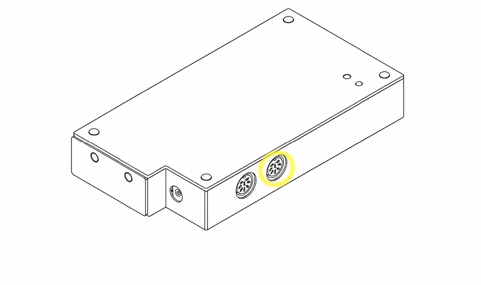
ConnectRound serial cable → MEM-200 Port 4

Connect Ethernet to the MEM (any LAN port) and Relay Box (any LAN port), then go to Parameters → Network → Others.

VERIFY

Port and cable are confirmed before moving or reconnecting any MEM cables.

SAFETY

Disconnect AC power before attaching or removing MEM cables.

Manual excerpt: Port 4 Diagram

Disconnect the AC adapter from the outlet before attaching/removing cables. Use the supplied adapter and cable clamp; do not move the unit with cables connected.

MEM-200 Operators Manual pp. 5–6, 16

MEM-200 rear-panel drawing with the right-hand round Serial Port 4 highlighted in yellow
MEM-200 Port 4 location shown here.

Shared folder · 1 of 2

Enter values below

PathParameters → Network → Other → Shared folder
  • Shared folder location = 192.168.0.120Enter this only as the shared-folder location; leave the MEM network address at its factory or existing site setting.
  • Folder name = DATA
  • Input folder type = MEM-200
  • Input of serial communications computer data = Master port 4Use the applicable slave port only when the approved site design uses a slave MEM.
IF THIS IS A FIRST-TIME DAISY CHAIN

Confirm the approved topology with your service manager and schedule technical support when needed.

Do not enter passwords here. Use only site-approved credentials; factory examples are not account settings.

Manual excerpt · MEM-200 p. 99

The RT-6100 Shared folder area lists the master computer name/IP, folder name DATA, Input folder type MEM-200, and the serial-computer-data input port.

MEM-200 Operators Manual p. 99

Access check · 2 of 2

Prove the shared-folder path

TEST

On the master MEM-200 Network settings screen, run the access check after entering approved computer/share information.

PASS

Access OK is shown beside RKT, LM, and RT; missing folders are created.

FAIL

Access NG means the share was not found. Confirm site-approved credentials, computer/share information, MEM power, and cable seating.

HARD POWER RESET THEN RETEST

Power down the RB and MEM. Power the MEM back up first, then restore RB power and rerun the access check.

Manual + field guide · MEM access test and reset

Access OK beside RKT, LM, and RT means the share is accessible and missing folders are created; Access NG means the share was not found. For this TRS install workflow, hard power reset the RB and MEM, powering the MEM back up first, then retest.

MEM-200 Operators Manual p. 26; Digital Refraction for Field Engineers p. 9

MEM / EHR is not being configured today. Leave network settings unchanged and continue to the selected pretest-transfer path, or go directly to Verify install if no pretest transfer is used.

Choose-one route · cable

Cable transfer: Pretest to exam room

Use this route only when pretest data travels through the master MEM-200. Keep the alternate one-cable topology closed unless it matches the approved site design.

Cable route · master lane

Choose the master lane

UseExam lane closest to the pretest room = Master Lane

Run each selected device’s 8-pin cable to that lane. Label both ends of each cable LM or AR as applicable.

Installation reference · Connection guide p. 2

The supplied connection guide uses the closest lane for the shortest cable run; a one-lane site uses the same setup.

Connecting LM-7 and TonoRef2 with TRS-6100 p. 2

Cable route · physical connection

Connect safely and secure the LM-7

  1. Power off each source device before attaching or removing its 8-pin communication cable.
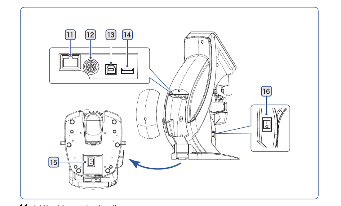
  2. For an LM-7, connect the cable at communication port 12, reinstall the rear cover, and secure it with the Phillips #2 screw.
  3. Run the selected LM and AR/TonoRef cables together to the Master Lane, keeping strain off each connection.
Manual excerpt · LM-7 pp. 75, 80

Power off connected equipment before attaching the communication cable. The LM-7 communication connector sits behind the rear cover; secure the cover after the cable is installed.

LM-7 Operation Manual pp. 75, 80; Connecting LM-7 and TonoRef2 with TRS-6100 p. 2

Cable route · MEM ports

Connect to the master MEM-200

Direct cable map for selected devices

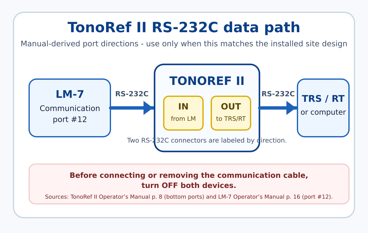
TonoRef II / ARKData-output RS-232C (OUT)
MEM-200Port 1
LM-7Communication port #12
MEM-200Port 2
Confirm the connections shown match the installed site design.
Alternate one-cable topology · only if installed this way

Path: LM-7 → TonoRef / ARK → master MEM-200. Use it only when the approved site design calls for the daisy chain.

SET BOTH DEVICES

The cable path alone is not sufficient. Complete the LM-7 and TonoRef communication values below before testing.

  • LM-7Printer = AR print · Com mode = NIDEK · Baud rate = 9600 · Parity = Odd · Data bits = 8 bit · Stop bits = 1 bit.
  • TonoRef II / ARKSet the LM input to NIDEK; I/F mode = NIDEK · I/F format = ALL · Baud rate = 9600 · Bit length = 8 · CR code = No · LM data print = Yes.

AR print sends the LM-7 data and prints it through the connected TonoRef / ARK. The direct dual-cable MEM route uses the normal LM-7 printer choice described below instead.

Connecting LM-7 and TonoRef2 with TRS-6100 pp. 3, 5; LM-7 Operation Manual pp. 82, 85; TonoRef II Operators Manual p. 94

Alternative TonoRef II RS-232C data flow from LM-7 communication port 12 through TonoRef II to the TRS or computer
Alternate daisy-chain path only; it is not the default direct dual-cable MEM plan.

Cable route · LM-7

LM-7 setup

Set toParameter 6 → Auto R/L = On
Parameter 13 → Single state = Off
Parameter 44 → Com mode = NIDEK

The current LM-7 manual numbers Com mode as 44. Older field guides may call it 43; follow the setting name Com mode if the installed software differs.

SET PRINTER FOR THE ROUTE

Off sends only to the external device. On prints locally and sends data. Use AR print only for the alternate LM → TonoRef / ARK chain.

VERIFY

Use the LM-7 Print action as the send trigger, then prove the TRS receives the data.

IF FAILED

Check Com mode, the Port 12 cable, printer setting, and the approved site topology before moving cables.

Manual excerpt · LM-7 pp. 81–85

Auto R/L changes to the opposite lens side when the locked lens is removed. With Single state off, Clear sets R rather than the single-lens state. Printer off transmits without local printing; On transmits and prints; AR print transmits and prints through the connected AR, ARK, or RKT.

LM-7 Operation Manual pp. 81–85

View LM-7 Port 12 diagram
LM-7 communication port overview including communication port 12
Use LM-7 communication port #12 for the pretest cable route.

Cable route · TonoRef II

TonoRef II / ARK setup

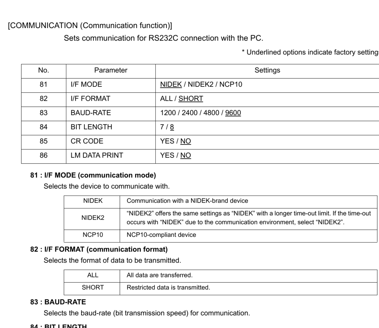
Communication targetsI/F mode = NIDEK · I/F format = ALL
Baud rate = 9600 · Bit length = 8 · CR code = No
  1. From the measurement screen, use R4 to reach Page 3, then hold the Parameter button for about one second.
  2. Select COMMUNICATION, then set the values above.
  3. Press the running-man Exit button twice to return to measurement and save the setting.

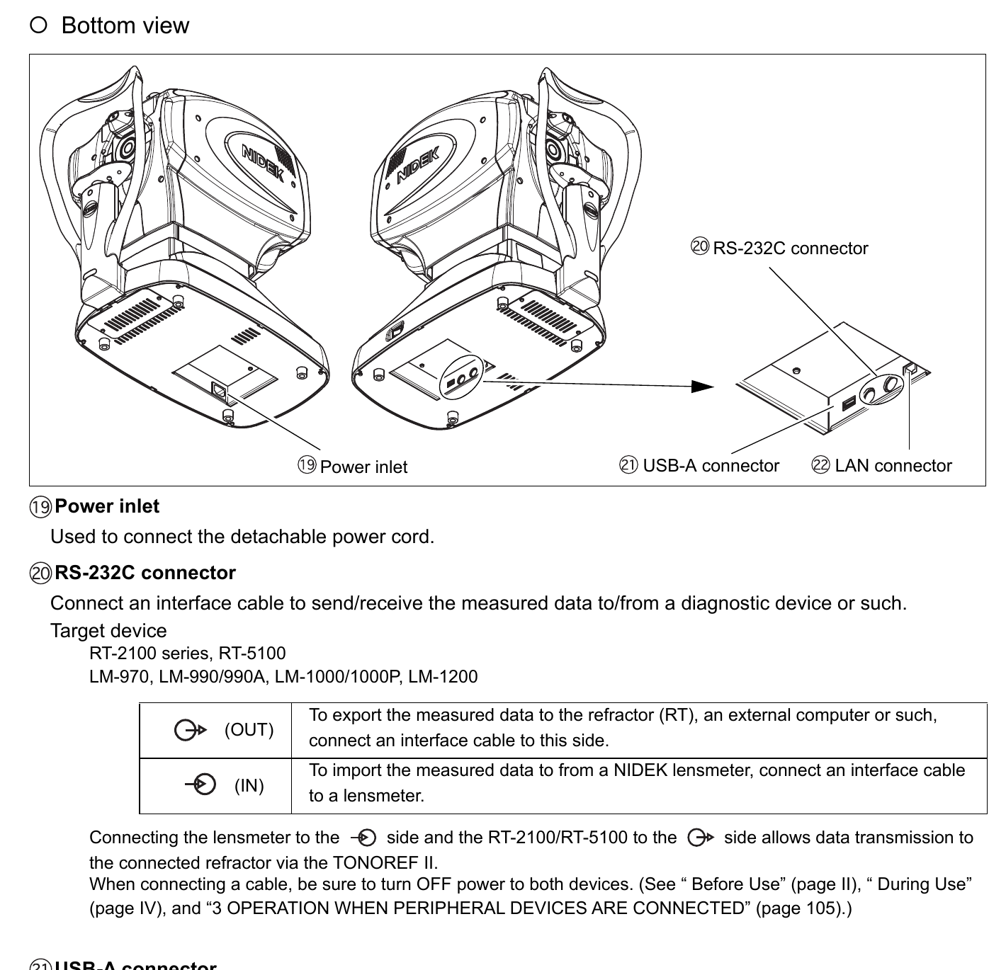
Set date/time and use the data-output (OUT) RS-232C connector—the right-hand port closest to the patient—for the cable path.

Manual excerpt · TonoRef II pp. 81–82, 94

The COMMUNICATION page sets I/F Mode, I/F Format, baud rate, bit length, and CR code. ALL transfers all data. The values are saved after Exit returns to the measurement screen.

TonoRef II Operators Manual pp. 81–82, 94; MEM-200 Operators Manual p. 59; Connection guide p. 2

View OUT-port and communication diagrams
TonoRef II bottom-view manual diagram showing RS-232C OUT and IN connections, USB, LAN, and power
For the cable path, use the RS-232C data-output (OUT) connector.
TonoRef II operator manual communication settings reference for I/F Mode and I/F Format
Communication-setting reference from the TonoRef II operator manual.

Cable transfer proof

Prove each selected source

Separate results
TEST

Use an approved test record. Make a pretest measurement, send it from the source device, then go to the correct TRS.

PASS

The correct data type arrives at the intended TRS with the expected record details. Confirm AR/ARK and LM paths separately when both are installed.

IF FAILED

Start with source-device communication setting, port/cable path, and master-lane topology. Do not move cables until the site design is confirmed.

Choose-one route · Eye Care card

Card Reader Data Transfer

The LM-7 has a built-in Eye Care card slot. TonoRef II uses a source reader that must match its label. At the TRS, use the built-in slot unless an external reader is actually installed.

Reader model check

Do not use “one down” DIP instructions

Required

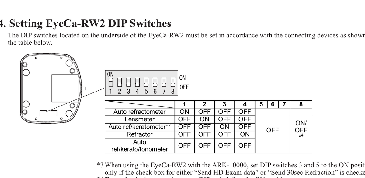
The setting depends on the reader model and the connected device. EyeCa-RW and EyeCa-RW2 manuals use different instructions. Do not merge them.

Manual excerpt · identify reader before setting DIP

EyeCa-RW2: its DIP chart uses a device-specific row. Older EyeCa-RW: the TonoRef II manual gives a different instruction. Read the label, then use only the matching manual.

EyeCa-RW2 Operator’s Manual p. 5; TonoRef II Operator’s Manual p. 114

View EyeCa-RW2 DIP chart
EyeCa-RW2 DIP switch table: auto ref kerato tonometer uses switches 1 through 7 off; external refractor uses 1 through 3 off, 4 on, and 5 through 7 off
Use the EyeCa-RW2 row only if the reader label confirms RW2. Switch 8 is a separate beep setting.

LM-7 · Eye Care card

Write LM data with the built-in card slot

  1. Insert an Eye Care card in the LM-7 while no measurement data is locked. The card icon changes from white to blue.
  2. Measure the right and left lenses, then press Print.
  3. Wait for the card icon to return from green to blue before removing the card.

Specify R/L; data is not written in the single-lens state. The LM-7 stores one pair of frames per card.

Manual excerpt · LM-7 p. 67

The LM-7 saves sphere, cylinder, axis, add, and prism for right and left lenses through its built-in Eye Care card slot. Green indicates card access; blue indicates it is ready to remove. Data is not written if the lens side remains in single state.

LM-7 Operation Manual p. 67

TonoRef II · Eye Care card

Set up the source reader

If the label says EyeCa-RW2Auto ref / kerato / tonometer row: 1–7 = OFF

For an older EyeCa-RW reader, stop and follow the matching EyeCa-RW/TonoRef procedure instead. Switch 8 is only the beep choice: on an RW2, ON disables the reader beep.

Manual excerpt · RW2 p. 5; TonoRef II pp. 114–115

On an EyeCa-RW2 connected to an auto-ref/kerato/tonometer, use the Auto ref/kerato/tonometer row. At the source reader, orange means access/writing; flashing green means complete. Do not remove the card while orange.

EyeCa-RW2 Operator’s Manual p. 5; TonoRef II Operator’s Manual pp. 114–115

View legacy EyeCa-RW connection illustration
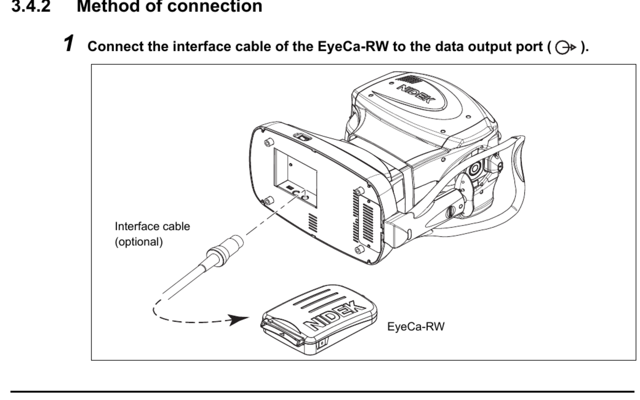
TonoRef II manual diagram showing the legacy EyeCa-RW interface cable connected to the data-output port
Legacy EyeCa-RW connection illustration. It is not the source for EyeCa-RW2 DIP settings.

Eye Care card · receiving end

Receiving reader at the TRS

Standard RT-6100 built-in card slotInsert the Eye Care card — AR/LM data imports automatically and the card is cleared.

A standard RT-6100 does not require an external RW2 reader or external reader DIP configuration at the refractor.

Conditional: external EyeCa-RW2 physically installed at refractor

Only when an external reader is actually installed and its label says EyeCa-RW2, use the RW2 Refractor row: 1–3 = OFF, 4 = ON, 5–7 = OFF. Switch 8 is the separate beep/mute choice.

EyeCa-RW2 Operator’s Manual p. 5

Manual excerpt · RT-6100 pp. 24, 48

The RT-6100’s Eye Care card reader imports AR/LM data automatically when the card is inserted and clears the card after reading.

RT-6100 Operation Manual pp. 24, 48

Eye Care card · transfer

Read each source at the TRS

  1. Write an Eye Care card using each selected source workflow above.
  2. Wait for the source device to finish accessing the card before removing it.
  3. Insert the card into the RT-6100’s built-in slot and confirm the matching AR or LM data imports.

LM-7 built-in reader: wait for the icon to return to blue before removal. LM-7 Manual p. 67

TonoRef II with EyeCa-RW2: wait for slow/flashing green before removal; do not remove the card while the reader is orange. EyeCa-RW2 Manual pp. 2–3

PASS

Each selected source completes card access, then the intended RT displays its AR or LM data.

IF FAILED

Confirm the source workflow, card/contact condition, and the RT receiving slot. For an external reader, check its model and matching device row.

Manual excerpt · LM-7 p. 67; EyeCa-RW2 pp. 2–3; RT-6100 p. 48

On the LM-7, wait for the built-in card icon to change from green back to blue. On an EyeCa-RW2 source reader, do not remove the card while orange; wait for slow green. The RT-6100 built-in slot imports AR/LM data and clears the card.

LM-7 Operation Manual p. 67; EyeCa-RW2 Operator’s Manual pp. 2–3; RT-6100 Operation Manual p. 48

Eye Care card · proof

Prove each selected source

Separate results
TEST

Use an approved test record: write source data to the card, read it at the intended TRS, and watch the source state.

PASS

The intended AR/LM data appears at the TRS. The selected source indicated completion before card removal.

IF FAILED

Recheck model-specific reader instructions, data source, card/contact condition, and the receiving slot/reader design before retrying.

Device support

Pretest device setup and manual reference

Use the route cards for required install values. Open the matching manual reference only when a site needs a different approved setting.

TonoRef II · card route

Set communication before card transfer

Set whenever TonoRef II is connectedI/F Mode = NIDEK · I/F Format = ALL · date/time correct · use OUT port

Set all four items whenever a TonoRef II is included in the installation. If any are missed, K readings will not transfer to the EHR. Also complete the source-reader setup in the Card Reader route.

Manual excerpt · TonoRef II pp. 8, 94

Communication settings are on the COMMUNICATION page. ALL transfers all data.

TonoRef II Operators Manual pp. 8, 94

LM-7

Cable communication check

Cable route
For cable transferParameter 44 → Com mode = NIDEK · use Port 12 · Print sends data

The current LM-7 manual numbers Com mode as 44. On earlier software, locate the setting by name if a different number is displayed.

Manual excerpt · LM-7 pp. 75, 84–85

Power down before connecting. Parameter → page arrows → setting → Exit saves the change; Print transmits measured data.

LM-7 Operation Manual pp. 75, 84–85

LM-7 · complete manual reference

All parameter settings

Reference
Manual options · LM-7 parameters 1–74

These are the complete LM-7 manual settings. The cable-route target stays: Auto R/L = On, Single state = Off, and Com mode = NIDEK. Use another value only for an approved site need.

Measurement and display · 1–15
  • 1. Step0.25, 0.12, 0.06, 0.01 D
  • 2. Cylinder+, ±, −
  • 3. PrismOff, P-B, BU/D BI/O
  • 4. Abbe selectA, B, C, Com
  • 5. Wavelengthe-line, d-line
  • 6. Auto R/LOff, On
  • 7. Auto read SOff; normal or large-cross auto-read threshold
  • 8. Auto read R/LOff; normal or large-cross auto-read threshold
  • 9. Distance auto readOff, On
  • 10. Near auto readOff, On
  • 11. Contact auto readOff, On
  • 12. IndicatorOff, On
  • 13. Single stateOff, On
  • 14. NearNear Sph, Add
  • 15. Contact measurementOff, On, Only
Print settings · 16–28
  • 16. PrinterOff, On, AR print; LM-7P uses On
  • 17. Print formatRight & Left, Left & Right
  • 18. Print density60, 80, 100, 120, 140%
  • 19. Print numberOff, On; 0001–9999
  • 20. Paper cutPartial, Full
  • 21. Auto cutterOff, On; LM-7P only
  • 22. Economy printOff, On
  • 23. Auto print SOff, On
  • 24. Auto print R/LOff, On
  • 25. Print & ClearOff, On
  • 26. Print date formatOff, Y.M.D, M/D/Y, D/M/Y
  • 27. QR codeOff, On; LM-7P only
  • 28. PD layoutOff, On; LM-7P only
Device functions · 29–40
  • 29. Initial screenAuto, Normal, Progressive, Contact
  • 30. TargetNormal target, Prism target
  • 31. GuideOff, On
  • 32. BeepOff, Low, Middle, High
  • 33. Auto offOff, 1, 3, 5, 10, 15, 30, 60 minutes
  • 34. ContrastLow, Middle, High
  • 35. ColorStandard, Change: 300
  • 36. TransmittanceOff, On, With
  • 37. Transmittance step1, 5%
  • 38. Transmittance displayCompare, Simple
  • 39. Auto correctOff, On, Silent
  • 40. USBHost, Device
Reader and serial communication · 41–57
  • 41. Read beginning of readerOperator 1–255; Patient 1–255
  • 42. Read length of readerOperator 1–16; Patient 1–16
  • 43. ID modeOff, PAT, OPE/PAT
  • 44. Com modeOff, NIDEK, NIDEK2, PC, NCP10, NCP20
  • 45. Baud rate1200, 2400, 4800, 9600, 19200 bps
  • 46. ParityOff, Odd, Even
  • 47. Data bits7 bit, 8 bit
  • 48. Stop bits1 bit, 2 bit
  • 49. CR codeOff, On
  • 50. Prism TxOff, On, Display
  • 51. SourceNumeric address; default 1
  • 52. DestinationNumeric address; default 0
  • 53. RequestTimeout seconds; default 2.0
  • 54. ReceptionTimeout seconds; default 10
  • 55. ResponseTimeout seconds; default 2.0
  • 56. Re-requestTimeout seconds; default 2.0
  • 57. RetryRetry count; default 3
Network and wireless LAN · 58–74
  • 58. LANOff, LAN, WLAN
  • 59. MAC addressDisplayed hardware address
  • 60. NetworkOff, On
  • 61. File formatNIDEK_V1.00, NIDEK_V1.01
  • 62. DHCPOff, On
  • 63. IP addressNumeric network address
  • 64. Subnet maskNumeric subnet mask
  • 65. Default gatewayNumeric gateway address
  • 66. User nameNetwork user name
  • 67. PasswordNetwork password
  • 68. DomainNetwork domain or workgroup
  • 69. PC nameDestination computer name
  • 70. FolderShared folder name
  • 71. Network timeoutOff, On; timeout value
  • 72. SSIDWireless network name
  • 73. Security modeOpen, WEP 128 ASCII/HEX, WEP 64 ASCII/HEX, WPA/WPA2 modes
  • 74. Security keyWireless network key

Network names, passwords, and keys are reference fields only. Enter only approved site values directly on the LM-7; do not put credentials in this guide.

LM-7 Operation Manual pp. 80–96

TonoRef II · complete manual reference

All parameter settings

Reference
Manual options · TonoRef II parameters 1–108

These are the complete TonoRef II manual settings. For this TRS workflow, use the route-specific Communication values: I/F mode = NIDEK, I/F format = ALL, baud rate = 9600, bit length = 8, and CR code = No.

AR and KM · 1–14
  • 1. Step0.01 D, 0.12 D, 0.25 D
  • 2. Vertex D.0.00, 10.50, 12.00, 13.75, 15.00, 16.50 mm
  • 3. Axis step1°, 5°
  • 4. Meas modeCON., NOR.
  • 5. AI modeYes, No
  • 6. AR continue3–10; factory setting 3
  • 7. AR thumbnailYes, No, Low Conf
  • 11. KM unitmm, D
  • 12. KM displayR1/R2, Ave/Cyl
  • 13. Ref. index1.3320, 1.3360, 1.3375
  • 14. KM continue3–10; factory setting 3
Non-contact tonometry · 21–30
  • 21. Set low confYes, No
  • 22. Low conf lv.Yes, No
  • 23. Low conf alarmYes, No
  • 24. Fix LED blinkYes, No
  • 25. NT continue1–10; factory setting 3
  • 26. Decimal digitYes, No
  • 27. ASHOT timingNormal, Fast
  • 28. Meas intervalShort, Normal, Long
  • 29. NT AI modeYes, No
  • 30. Delete selectTime, Data
Print 1–3 · 31–56
  • 31. PrintManual, Auto, No
  • 32. Econo. printYes, No
  • 33. Print & ClearYes, No
  • 34. Print densityLow, Middle, High
  • 35. Patient no.Yes, No
  • 36. Set patient no.0001–9999
  • 37. Name printYes, No
  • 38. Date formatY/M/D, M/D/Y, D/M/Y, No
  • 39. Print commentYes, No
  • 41. AR printAll, Short
  • 42. KM printAll, Short, All (KM)
  • 43. Conf. indexYes, No
  • 44. Error dataYes, No
  • 45. CAT markYes, No
  • 46. Error printYes, No
  • 47. NT printV, H, No
  • 48. Print formatR→L, AR→KM
  • 49. AR/NT cutYes, No
  • 51. SE printYes, No
  • 52. Eye printYes, No
  • 53. TL printYes, No
  • 54. CL printYes, No
  • 55. Near PD printYes, No
  • 56. Working D.14–28 inches, in 2-inch increments
Functions · 61–75
  • 61. Window checkYes, No, Day
  • 62. Tracking SWTRC/ASHOT, ASHOT On, ASHOT Off
  • 63. Auto PDYes, No
  • 64. Sleep5 min, 10 min, 15 min, No
  • 65. BeepLow, High, No
  • 66. AR brightnessNormal, Light
  • 67. NT brightnessNormal, Light
  • 68. Icon offYes, No
  • 71. Pressure checkYes, No, Day
  • 72. Change modeAuto, Manual
  • 73. Change speedLow, High
  • 74. Target typeRKT, AR/NT
  • 75. Too close beepYes, No
Communication and reader · 81–92
  • 81. I/F modeNIDEK, NIDEK2, NCP10
  • 82. I/F formatAll, Short
  • 83. Baud-rate1200, 2400, 4800, 9600
  • 84. Bit length7, 8
  • 85. CR codeYes, No
  • 86. LM data printYes, No
  • 91. Reader start1–250
  • 92. Reader length1–14
Network · 101–108
  • 101. NetworkYes, No, ACK
  • 102. DHCPYes, No
  • IP / Mask / GateIP address, subnet mask, default gateway
  • 103. UserUser name up to 17 characters
  • 104. PasswordPassword up to 17 characters
  • 105. DomainNetwork domain
  • 106. PC nameComputer name up to 17 characters
  • 107. FolderShared-folder name up to 17 characters
  • 108. Image sendYes, No, Low Conf

Network user and password fields are reference fields only. Use approved site credentials directly at the instrument; do not record credentials in this guide.

TonoRef II Operators Manual pp. 81–100
Only if M3 is installed

Measurement / aiming quick note

Optional
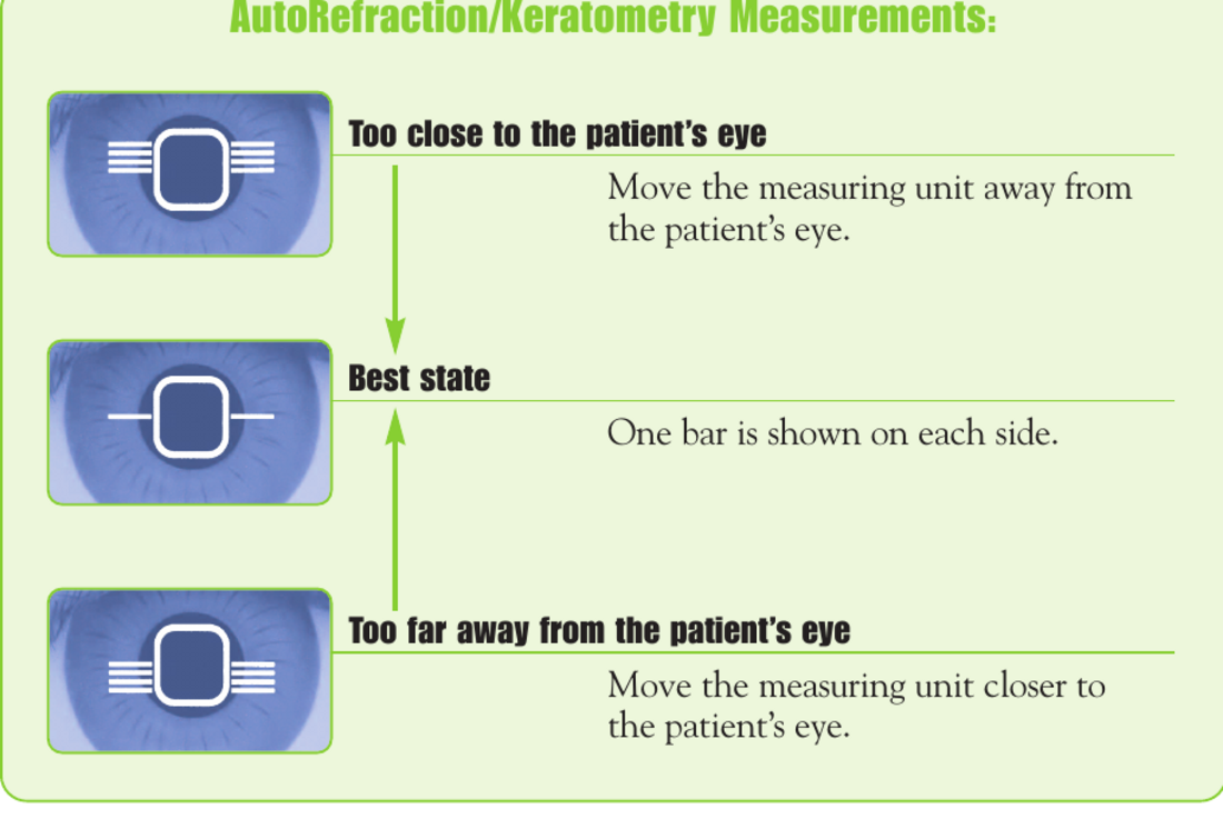
AimOne bar on each side = best AR/K aiming state

The M3 takes three K and AR readings and displays FINISH when complete. If KM appears, have the patient blink and press the top joystick button again; if PD err appears, clean the chinrest PD sensors.

Manual excerpt · M3 User Guide p. 1

M3 User Guide p. 1

View M3 alignment diagram
M3 autorefractor and keratometer alignment states showing too close, best state, and too far
M3 AR/K alignment reference.

4. FARS · TS-610 only

FARS quick reference

FARS means Fully Assisted Refraction System. Select it only for a TS-610 install; it is not a connection option for RT-6100 / TRS-6100.

FARS

Open the Quick Guide

Reference

Use the supplied FARS Quick Guide for the joystick controls, measurement flow, and patient-response reference. It is available offline with this guide.

Open FARS Quick Guide

Fully Assisted Refraction System Quick Reference Guide, pp. 1-2

Device support

SC-1600 chart and IR emitter

Set the chart at its underside buttons, then match the TRS controller to the emitter installed in the room.

SC-1600 · at the chart

Enter the menu and set the room

  1. Hold any one of the four buttons under the SC-1600 for about 3 seconds. The setting screen appears.
  2. Use 1 ↑ and 2 ↓ to move through items, 3 ↔ to move between fields, and 4 CHANGE to change a value.
  3. Set Chart type to the installed Marco refractor choice. The selected choice must end in M for Marco.
  4. Set Distance to the actual path from the patient’s eye to the LCD. With a mirror, measure the reflected path.
  5. Set Mirror = ON for a mirrored throw; set OFF for a straight throw.
  6. Set Beep sound = Off.
  7. Move to EXIT with 2 ↓, then press 4 END to finish.
  • SC-1600 chart type = installed Marco refractor choice ending in MThe M suffix identifies Marco.
  • Distance = actual eye-to-LCD pathSelecting a chart type sets 5 m by default. Measure the room and change it; the manual recommends at least 3 m.
  • Mirror = ON for a mirrored throw · OFF for straight throw
  • Beep sound = Off
Manual excerpt · SC-1600 pp. 55–57, 116–118, 122

Hold an underside function button for three seconds. Buttons 1/2 move up/down, 3 moves between fields, and 4 changes a setting. At EXIT, button 4 becomes END. The Distance setting follows the patient’s eye-to-display path; mirror installations use Mirror ON to reverse the chart image.

SC-1600 Operators Manual pp. 55–57, 116–118, 122

View the four-button map
1 ↑far left
2 ↓second
3 ↔third
4 CHANGEfar right · END at exit
Function buttons under the SC-1600, viewed left to right. SC-1600 Manual p. 55.
Manual options · SC-1600 chart settings
  • Chart typeSelect the installed Marco refractor choice. The choice must end in M, which identifies Marco.T, M, P, UK, PhM
  • DistanceEye-to-LCD path, 1 cm increments.2.50–6.00 m; up to 7.00 m in Type M
  • MirrorReverse the chart image for a mirrored optical path.ON, OFF
  • Beep soundVolume for chart operation.High, Low, Off
  • RemoteOFF when the chart is connected to a motorized refractor; I when the optional remote is used.I, OFF
  • Remote channelMatch the optional chart remote when used.1ch–8ch

SC-1600 Operators Manual pp. 56–57, 116–119

TRS controller · chart link

Set the link for the installed IR emitter

Controller pathSide menu → Setting → Parameters → page 10/10 (Other 3) → Chart link (SC series)
BLACK M&S IR EMITTER

Set the TRS to Wired (the controller/manual Cable choice).

WHITE NIDEK IR EMITTER

Set the TRS to Wireless 8.

These are the field setup targets for an SC-1600 with the corresponding emitter. Match the hardware in this room, then prove the chart changes from the controller.

Manual excerpt · RT-6100 p. 230

The RT-6100 lists Chart link for SC series under Parameter: Other 3. The manual labels its choices Cable, Wireless 1–8, and No.

RT-6100 Operation Manual p. 230

Manual options · Chart link (SC series)
  • CableThe manual’s wired choice. Use this field target with the black M&S IR emitter.
  • Wireless 1–8The manual’s wireless-channel choices. Use Wireless 8 with the white Nidek IR emitter.
  • NoChart communication disabled; not the field target for either emitter above.

RT-6100 Operation Manual p. 230; field setup targets supplied for M&S and Nidek emitters

Chart proof

Test from controller to chart

TEST

Call a chart from the controller and confirm it changes at the expected display.

PASS

The expected chart appears, brightness is even, orientation matches straight or mirrored throw, distance matches the room, the selected chart type ends in M for Marco, and the chart beep is off.

IF FAILED

Confirm chart type, Chart link setting for the installed emitter, power, and installed path before changing other settings.

Prove the install

Final verification

Mark checks only after observing the result. The progress count follows the selected route.

Always required

Room-ready checks

0 complete

MEM / EHR proof

Confirm the path beyond the access check

TEST

Use an approved non-patient test record. Use the site’s configured Output behavior (one or two presses), then check the intended destination.

PASS

Confirm the expected destination receives the record. Do not store patient data in this guide.

IF FAILED

Return to Access check, hard power reset RB/MEM with MEM first, then correct approved network/share details before retrying.

Field guide · Data-output proof

Use random test values to confirm transfer. The configured Data list at output setting determines whether Output requires one or two presses. If Marco Connect is installed and connected to MEM Port 4, verify the file populates there; otherwise verify the appropriate approved test destination.

Digital Refraction for Field Engineers p. 10

Example of MEM connection
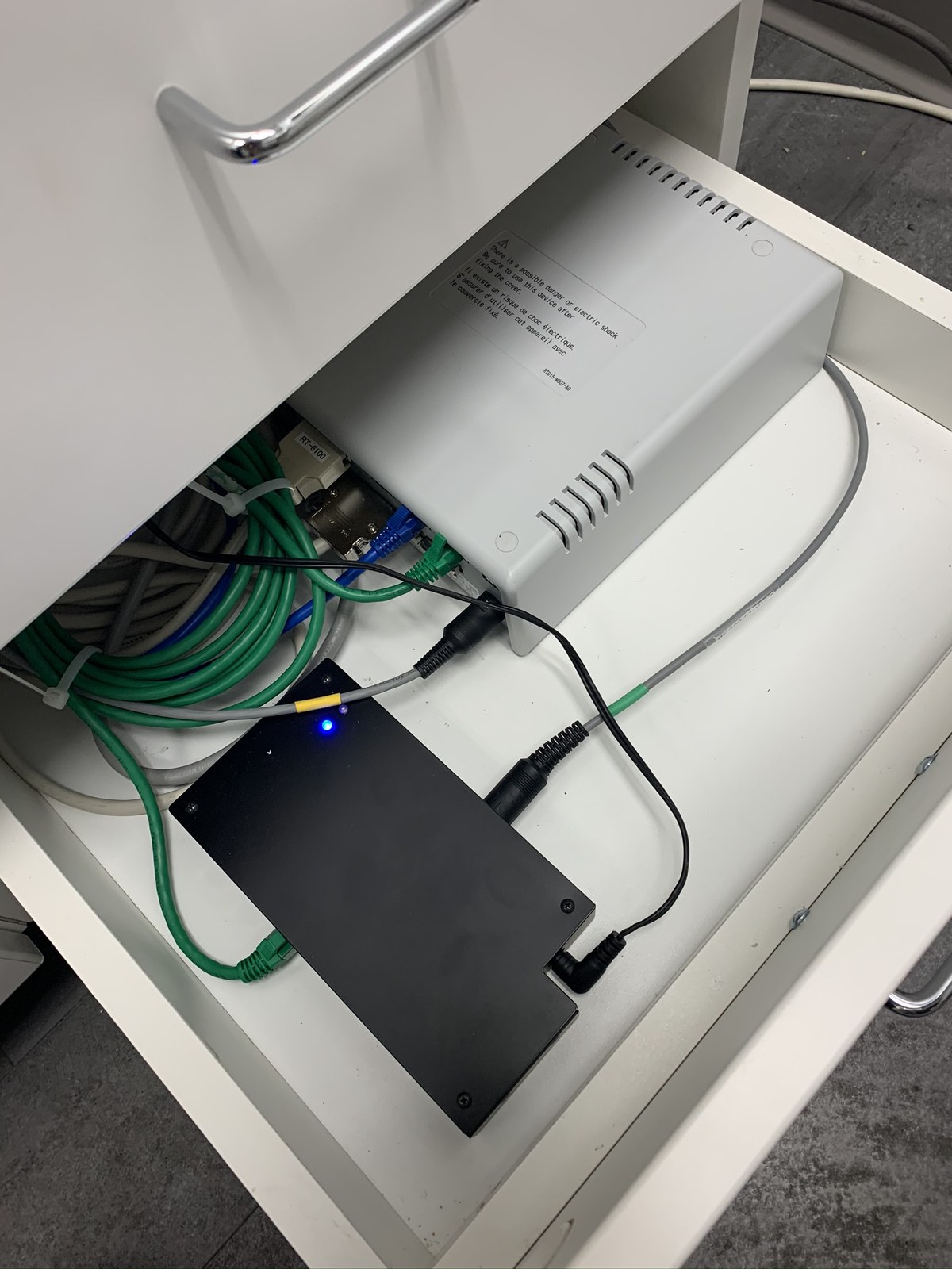
Example drawer-mounted MEM-200 with relay box and cabling installed neatly in a cabinet
Example of MEM connection. A photo records the cabinet layout; use the data-output test to prove transfer.

Return to MEM access check

Route proof recap

Review completed transfer and chart tests

Training handoff

Leave the clinic ready

4. FARS · TS-610 only

Set up SSC-100 / SSC-100M Space Saving Chart

Use this path only for a TS-610 with an SSC-100 or SSC-100M. SSC means Space Saving Chart; it is not the standard SC-1600 setup.

Open this first

Chart Selection document

Required

Before changing either device, open the chart-selection sheet. The required matched pair is RT-6100: SC-100 type M and SSC-100: Chart type M.

Open Chart Selection document

TS-610 (SSC-100M & RT-6100) Chart Selection Instructions, pp. 1-2

Required pairing

Set both sides to M

DO NOT MIX CHART TYPES

If the RT-6100 shows “chart doesn't work,” complete the two matching selections below before troubleshooting anything else.

RT-6100Chart Selection = SC-100 type M
SSC-100 / SSC-100MParameter 1 Chart type = M

The SSC-100 manual identifies M as the United States chart type and says the SSC chart type must match the control box.

TS-610 / SSC-100 procedure

Match the RT-6100 and Space Saving Chart

1. Set the RT-6100 chart selection

  1. During the RT-6100 initial Chart Selection, choose SC-100 type M.

2. Set the SSC-100 chart type

  1. At the RT-6100 Home screen, press the upper-left Arrow, then select Setting.
  2. Select Parameter setting for chart, then select Yes. The parameter screen appears on the SSC-100 display.
  3. If the SSC-100 screen is hard to read, use a phone camera and zoom in. Use 1 ↑, 2 ↓, and 3 ↔ to place the cursor on 1 Chart type.
  4. Select M, then press 4 CHANGE to confirm. Select EXIT (or the Return control) to leave the parameter screen.

3. Prove the match

  1. From the RT-6100, select the next chart once after exiting. The SSC-100 manual notes that the chart window may not update until the next chart is selected.
  2. Confirm the “chart doesn't work” message has cleared and the expected chart appears. If it does not, recheck both required M selections before changing cabling or other settings.
Manual confirmation · why M is required

The SSC-100 operator's manual lists M as the chart type for the United States. Its Chart type setting must be the same as the control box. The RT-6100 path opens the SSC parameter screen after Setting → Parameter setting for chart → Yes.

SSC-100 Operator's Manual pp. 41-45; Chart Selection Instructions pp. 1-2

Advanced only

Copy settings to lanes or a loaner CB

Use this only for approved multi-lane or loaner-controller work. It is not part of a normal first install.

Export / import TRS settings · rare / manager-approved

Export from the source controller

  1. Open Parameter settings.
  2. Select Export at the bottom of the screen.
  3. Select OK.
  4. Press End twice, then remove the SD card from the source CB.

Import to the receiving controller

  1. Insert the copied SD card into the receiving TRS CB.
  2. Select Import at the bottom of the CB screen.
  3. Select OK.
  4. Press End twice to exit Settings, then perform the approved hard reset/power cycle.
  5. Return the original SD card to the source CB.
IMPORTANT

Import replaces the receiving TRS’s parameter settings. If both units are on the same network, delete RT015CB_NETWORK.dat from RT015CB_BACKUP on the SD card before importing. (This is rare.)

VERIFY

Open the receiving controller, confirm the intended parameter targets, then complete the appropriate route-specific proof test.

Base TRS-6100 Total Refraction System Optimal Settings guide · Export / Import settings section

Reference files

Document Bank

Download the field references you need. These files are available for every install.

Diagram